All Posts (9)
Salve a tutti,
mi sono iscritto a questa comunità, anche se non so ancora bene come funzioni… Perdonatemi se faccio qualche CZ ! ;-)
Comunque, vorrei apportare un piccolo contributo con la mia modesta esperienza.
Qualche anno a dietro, andando in villeggiatura in auto, ero in coda sotto il sole rovente,
mi scatta l’ispirazione del volatile !
I quad erano agli albori, qualcuno osava mettendo insieme qualche giroscopio, altri deviavano verso un tricottero…. Tutto molto affascinante per me che stavo cominciando la mia carriera da modellista!
Di mestiere faccio e ho sempre fatto il tecnico AF, ma la micro-meccanica e l’elettronica ha sempre rapito la mia attenzione.
In quella calda giornata di Luglio, chiamai al telefono il mio amico Gianni, modellista veterano, mente brillante con nozioni di fisica, scatta la prima domanda… perché i quad sono così goffi e instabili? Analizzando le caratteristiche, attribuimmo tutto ai giroscopi e soprattutto alle latenze nella correzione d’assetto, dovute all’inerzia del blocco motore/elica.
Come migliorare tutto questo… un quad a passo variabile?, Si...
Lasciando giri costanti si poteva variare il passo, per correggere non bisognava aspettare che i rotori prendessero giri, ma avendo già il motore a regime, si aveva una riserva di energia “Pronta” per essere convertita dalle eliche a passo variabile, fin qui tutto filava come l’olio, anzi si poteva usare un solo motore per la propulsione, con tutti i benefici che ne potevano derivare.
Facendo due conti con le rotazioni e le coppie, cominciarono i primi problemi che aumentarono quando entrarono in gioco le miscelazioni … Il progetto fù abortito sul nascere….
Nei giorni a seguire, dagli e ri-dagli il quadricottero a passo variabile non voleva abbandonare la mia mente, e pian pianino, furono superati tutti quei lati oscuri che almeno teoricamente trattenevano a terra il quad.
Risolti, anche se con qualche riserva da verificare in seguito, tutti i problemi legati alla gestione meccanica, decisi di provare ! Investendo tempo e denari nella costruzione di un simulacro, per verificare la teoria.
Cominciai a buttare giù qualche appunto sulla costruzione, e a disegnare i vari pezzi del corpo centrale, cominciando dalla scatola cambio, dove avviene la riduzione e l’inversione delle rotazioni
Cercai di ridurre al massimo i costi, anche perchè c’erano quei dubbi purtroppo fugabili solo con un test-fly…
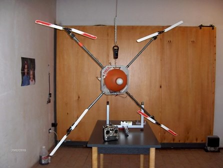
Qualche mese, e…Meccanica pronta, alimentata da due motori elettrici … mancava il “pilota”.
Cominciai una nuova avventura cercando qualcuno che mi facesse un software dedicato per il mio maxi-quadricottero !
CARATTERISTICHE HG3 :
4 eliche di 70 cm ciascuno è possibile utilizzare elica fino a 120 cm.
Dimensioni: 2,50 x 2,50 mt
Alimentazione: 12s Lipo
Motori 2 Potenza totale sono : 4400 W
Peso 6,5 Kg al decollo


Tante persone si spaventavano vedendo quella macchina che aspettava solo un po di software, un progetto senza dubbio molto impegnativo, ma non impossibile, comprai un po di hardware e sistemi di sviluppo, preso dalla disperazione, tentai il fai da te, ma ovviamente non sono programmatore e a 45 anni non si può imparare, tra una prova e l’altra, il quad è rimasto appeso al chiodo per circa due anni, fino a quando non mi sono imbattuto in un forum, e in un certo REDFOX… Il nome non ispirava molta fiducia, ma dopo tante, decisi di provai anche questa.
Contrariamente al suo nick Roberto, per quanto mi riguardi, è una persona simpatica, molto disponibile, competente e umana!
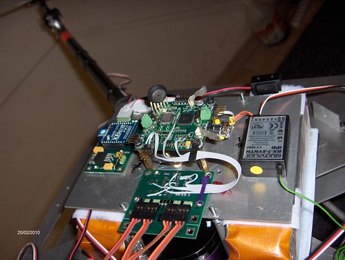
C’è stato da subito un certo feeling, ed insieme in poche settimane abbiamo messo a punto un hardware capace di pilotare la mia macchina, che da allora ho battezzato HG3.

Pochi test sono bastati a capire che poteva volare, e dopo il terzo tentativo ecco i risultati.
HG3 è servita a testare il mio progetto e la scheda di controllo, adesso ha lasciato il tavolo per essere riappesa al chiodo, lasciando il posto al suo successore HG3.2
Riguardo HG3 troverete info anche qui.
HG3.2 sarà una macchina ideata per “alzare peso” e sperimentare altre fonti di propulsione…
Per ora è tutto
Giuseppe D’Angelo
(Pipposoft)
HG3 l'era del quad a passo variabile è iniziata !
Multi-Pilot Base Board
- 3 Gyro ADXL 610
- ACC LYS 344
- 2 Serial
- Port 1
- SPI 1
- I2c
- 7 ESC OUT
- 1 Serial PPM in
Multi - Sensor / Navi
You need this board configuration for automatic navigation.
4 Ir-Sensor
1 Ultrasound range finder
1 Magnetometer
1 GPS 54 CHN 10 HZ
Hello everyone,
- Aeroquad
- Arduimu.
- Arducopter.
The LN MultiBoard 1.0 board details :
- AVR 644P (Sanguino compatible micro)
- 1 Power Switching da 8-30 Volt 3 Amp.
- 3 mems gyroscope 220 °/s
- 1 Accelerometer a 3 Axis X Y Z 2 G.
- 2 Pressure sensor 20 cm of resolution.
- 4 PPM Output Servo PPM 5 Volt using 4017 TTL LOGIC.
- 2 PPM Ouptup using standard ServoTime2 / ServoTimer PWM Library.
- 1 I2C Bus for motor control( LN BL Controller 20 Amp.)
- 1 Serial BUS TTL
- 1 SPI BUS TTL
- 1 Speaker Output.
- 2 Digital Output genarl pourpose.
- 1 PPM Input for R/C Controller.
Details
visit the site of company that develop LN Multipilot 1.0 http://www.lasernavigation.it visit https://www.youtube.com/rnavoni to see LN Multipilot 1.0 in action. visit http://code.google.com/p/aeroquad/
I'm starting to support the project the goal is to port Aeroquad
firmware on MultiPilot


This article is take from DiyDrones Post , original article Posted by Michal B on February 1, 2009 at 2:00pm
Here is another ArduPilot simulation inspired by Jordi's
simulation.
My simulation requires minimum additional hardware, all you need is
ArduPilot connected by FTDI cable to PC.
Actual simulation runs in X-plane simulator. ArduPilot get simulated GPS
data over serial, and it returns back proposed servo positions back
over serial as part of telemetry info (servos can also move physically).
ArduPilot also reports bunch of variables - lat/lot/alt, next waypoint,
distance to it, etc.
What you need to repeat the simulation:
- Modified ArduPilot code from this
blog post
- X-plane 9 demo
(buy full version if you wish, but demo works just perfect, it only
ignores joystick input after 10 minutes, but we control it other way so
it really doesn't limit us)
- Google Earth
- ArduSimulator ArduSim_20090211.zip
(developed by me), which is simple application that does following:
1) Connects to ArduPilot over serial for sending/receiving data
2) Connects to X-plane on localhost (same PC)
3) Reads data from X-plane (lat/lon/alt/course), sending these to
ArduPilot as GPS sentences
4) Simulating FMA copilot stabilization on ailerons/elevator
5) Reads and displays telemetry and servo positions from ArduPilot
6) Sends servo positions to X-plane to control throttle and rudder
7) Records fly path and sends it to Google Earth to display
Here's how to repeat the simulation:
- Start X-plane, go to Menu->Settings->Net Connections, select tab
Inet 3 and enable "IP of data receiver", change IP address to 127.0.0.1
and port to 49001. It looks like this: - Select Aircraft from folder Aircraft\Radio Control\GP_PT_60 (yes, we
want to fly RC plane which has ail/elv/rud/thr controll)
- Select airport Innsbruck
- You can open this KML path: Innsbruck.kmz
in Google Earth, which was my testing fly plan configured in ArduPilot;
this will show you the waypoints
- upload compiled ArduPilot code to the board and leave it running; LOCK
LED should keep flashing
- start ArduSim.exe (simulator tool); it will connect to serial port and
X-plane; if it can't connect to serial, specify correct port and
baudrate and press Start button
- click [Google Earth] button in ArduSim to make connection with GE
- hit B in X-plane to release brakes, and try keys A/W/C to choose
various views
Now simulation should be running if everything is connected
successfully, and you should see plane in X-plane to fly and
visualization path & icon in Google Earth to move. Don't control
plane in X-plane! ArduPilot will take-off and fly on its own.
Here's video how it all looks in action:
And complete flight path visualization for Google Earth: Flight.kmz
You can see original waypoints in white, and real fly path in yellow.
And also final circulation over start point when all waypoints were
visited...
Now about problems and future tasks:
- I have strong impression that controlling altitude by throttle with
use of copilot stabilization doesn't work properly, this simulation
showed me that plane didn't want to drop altitude from high point to
lower one... see results in above flight path in GE. I'm not sure how
real plane behaves (didn't went out to real world with this yet), we'll
see.
- For this reason I plan to start playing with complete stabilization in
ArduPilot, and controlling both elevator+throttle to get desired
altitude.
- You can play with dozen of various parameters to control behavior,
most obvious are PID settings for throttle/rudder in ArduPilot, but also
PID values in stabilization (which is here provided by simulator tool,
in real world it is FMA Copilot which you can control by its sensitivity
setting). Then you can change maximal servo rotation for ArduPilot to
work with. All these values make the plane fly smoother, make more
precise turns, etc etc. And the settings seem to depend on actual
aircraft and its physical behavior. So there won't be single settings
working for everyone.
- It's somehow cumbersome to specify different altitude for various
waypoints; while I converted waypoints from KML file out of Google
Earth, I had to specify individual altitudes manually in waypoints.h
file in ArduPilot code.
After all, I'm pretty happy to see the plane flying in simulator and
doing the task! Note that it's ArduPilot doing the navigation work. And
in a real airplane, this simulation allows to reuse the ArduSim
application as a base station, getting telemetry from plane over Xbee
modem and displaying what it does as well as showing path in Google
Earth.
This is an example of what we do with my friends Davide and Simone one years ago , Davide use the picture doing with FOX II for develop a model of river with a resolution of 2 mm:
There are also other example of photogrammetry application this is another that i found on youtube :
FoxTeam is an international Group that support the porting of different kind of arduino fly application and library to Multipilot Framework supported Board :
- Aeroquad Shield (Arduino Board + Custom Shield): http://aeroquad.info/bin/view/Main/PartsList_v2
- Mikrokopter FC2.0: http://www.mikrokopter.de/ucwiki/FlightCtrl
- Multiboard: http://code.google.com/p/lnmultipilot10/wiki/multiboard
- MultiNaviExp: http://code.google.com/p/lnmultipilot10/wiki/MulboarNaviExp
- PhiFUN Project: http://code.google.com/p/lnmultipilot10/wiki/PhiFUN_HEXA_Project (New)
This is an a framework of code selected for people that want to use wire languange and Arduino Framework to develop application where need mems component as Gyro , Accelerometer , Pressure sensor , servo motor , rx r/c ecc.
Link to user Prokject:
* Redfox HexaFox? : first test on Vector Force Table on MultiBoard and Aeroquad software http://code.google.com/p/lnmultipilot10/w/edit/VectorForceTable
* Redfox Multicopter FOX I-II-III http://code.google.com/p/lnmultipilot10/wiki/FOX_Project
* Pipposoft Mega Quad variable Pitch: http://code.google.com/p/lnmultipilot10/wiki/MultipilotHG3
* Aosen Variabile Pitch Project Tricopter / Quad , in early stage http://code.google.com/p/lnmultipilot10/wiki/MRVP_Platform (New)
* Jijuja Project a Multipilot upgrate to 20 Mhz of clock http://code.google.com/p/lnmultipilot10/wiki/Jijuja_Project
* Matrix Project a Great Okto Frame Project : http://code.google.com/p/lnmultipilot10/wiki/Matrix3D_Coaxial_OktoKopter_Frame_Project (New)
The support forum thread are :
http://www.arduino.cc/cgi-bin/yabb2/YaBB.pl?num=1264932579 (Italian )
http://www.rcgroups.com/forums/showthread.php?t=1187308 (International Eng.)
http://carancho.com/AeroQuad/forum/index.php?topic=131.0 (International Aeroquad discussion)
http://diydrones.com/profile/RoberoNavoni (International DiyDrones? Community)
http://groups.google.it/group/multipilot (Private Group only for Multipilot Developer)
Contact me for more info : lasernav@gmail.com or r.navoni@radionav.it